GPIO'S in embedded Rust
Using GPIO’S in embedded Rust
If you haven’t had a chance to look at the previous tutorials, we will start from the same project setup that was used in the in the first part of this series, if you don’t want to go back and look this is what it looks like:
#![no_std]
#![no_main]

use cortex_m_rt::entry;
use panic_halt as _;
use stm32l4xx_hal::{delay::Delay, pac, prelude::*};

#[entry]
fn main() -> ! {
    // Get a singleton to the peripherals of our device
    let p = pac::Peripherals::take().unwrap();
    // Get a singleton to the CorePeripherals of our device. Coreperipherals differ from Peripherals
    // the CorePeripherals are common to the cortex-m family.
    let cp = stm32l4xx_hal::device::CorePeripherals::take().unwrap();
    // From my understanding the constrain method works to provide different methods from the HAL on each of it's members
    let mut flash = p.FLASH.constrain();
    // Acquire clock control handle
    let mut rcc = p.RCC.constrain();
    // Acquire power control handle
    let mut pwr = p.PWR.constrain(&mut rcc.apb1r1);
    // Set the system clock and the peripheral clocks and enables them via freeze.
    let clocks = rcc
        .cfgr
        .sysclk(80.MHz())
        .pclk1(80.MHz())
        .pclk2(80.MHz())
        .freeze(&mut flash.acr, &mut pwr);
    // On our board the LED is tied to the PA5 pin. So we will need to get access to the GPIO A bank
    // The registers for GPIO A are controlled by the AHB2 (Advanced High-performance Bus 2)
    let mut gpioa = p.GPIOA.split(&mut rcc.ahb2);
    // We configure the user_led to be a push pull output.
    let mut user_led = gpioa.pa5.into_push_pull_output(&mut gpioa.moder, &mut gpioa.otyper);
    // We create a delay timer using the SYST peripheral
    let mut timer = Delay::new(cp.SYST, clocks);
    loop {
        // We use the Toggleable trait to turn on and off the led
        user_led.toggle();
        // We delay for 500ms
        timer.delay_ms(500_u16);
        // Repeat
    }
}
I’ll be using the NUCLEO-L476 for this post and will mostly utilize the on board button and LED for most of this tutorial. Since we’ve already reviewed how we can setup a simple push pull output. We will skip straight to input’s. The button on my board is connected to the PC13 pin. So we will need to get access to the GPIOC bank we can do this by adding the following to the code above:
    // Get a handle to the GPIOC bank
    let mut gpioc = p.GPIOC.split(&mut rcc.ahb2);
Now that we have our handle to the GPIO bank we need to actually configure the pin we want to use in our case PC13. The button on this board is open when the button state is idle and it is shorted to ground when the button is pressed. So we will want to use the pin as a pull up input. We can do so by adding the following:
    // Declare PC13 as a pull up input and grab a mutable reference to it
    let mut user_btn = gpioc.pc13.into_pull_up_input(&mut gpioc.moder, &mut gpioc.pupdr);
And that’s it now we will simply poll the button state and when the button is not pressed we will turn the LED on and when it’s pressed we will turn the LED off. We can do so by changing the loop code to the following:
    loop {
        // Check if the button is pressed (shorted to GND)
        if user_btn.is_low() {
            // Set the LED state to LOW
            user_led.set_low()
        } else {
            // Set the LED state high if the button is logic high
            user_led.set_high()
        }
    }
If you flash the code to the board and hit the button you should see the LED change whenever the button is pressed.
Interrupt’s
Now that we have a basic polling input setup let’s see what we would need to do in order to turn this into an interrupt. Turns out not much, let’s first create a global variables that we will use inside of our interrupt.
use stm32l4xx_hal::{
    pac,
    prelude::*,
    interrupt,
    delay::Delay,
    gpio::{Input, Edge, ExtiPin, gpioc::PC13, PullUp, gpioa::PA5, Output, PushPull},
    stm32
};
use core::cell::RefCell;
use core::ops::DerefMut;

// Button Global Variable
static BUTTON: Mutex<RefCell<Option<PC13<Input<PullUp>>>>> = Mutex::new(RefCell::new(None));
// Led Global Variable
static LED: Mutex<RefCell<Option<PA5<Output<PushPull>>>>> = Mutex::new(RefCell::new(None));
We needed to pull in the relevant Structs, Types, and Traits as well as declare our global variables so that we can access the resources inside or our interrupt. We then use the methods associated with our pin to configure it as an interrupt. We want a falling edge if we want the interrupt to trigger whenever the button is pressed, and we remove all of the code from our main loop so that the pin state is only changed within the interrupt.
    // Make the pin an interrupt source
    user_btn.make_interrupt_source(&mut p.SYSCFG, &mut rcc.apb2);
    // Enable the interrupt
    user_btn.enable_interrupt(&mut p.EXTI);
    // Trigger when the button is pulled from high to low
    user_btn.trigger_on_edge(&mut p.EXTI, Edge::Falling);
    // Enable interrupt
    unsafe {
        NVIC::unmask(stm32::Interrupt::EXTI15_10);
    }
    // Place the resources inside of their global variables
    free(|cs| {
        BUTTON.borrow(cs).replace(Some(user_btn));
        LED.borrow(cs).replace(Some(user_led));
    });

    loop {
    }
Then the last thing we do is write the interrupt handler.
#[interrupt]
fn EXTI15_10() {
    free(|cs| {
        // Get reference to the button
        let mut btn_ref = BUTTON.borrow(cs).borrow_mut();
        if let Some(ref mut btn) = btn_ref.deref_mut() {
            // Check to see that the interrupt is associated with our PC13 line
            if btn.check_interrupt() {
                // Clear the interrupt so that it doesn't fire again immediately
                btn.clear_interrupt_pending_bit();
                // Get the mutable led reference
                let mut led_ref = LED.borrow(cs).borrow_mut();
                if let Some(ref mut led) = led_ref.deref_mut() {
                    // Toggle the led
                    led.toggle();
                }
            }
        }
    });
}
The code for this is fairly straight forward. If you flash your MCU you should see that each time you press the button the LED state is toggled. Full code below.
#![no_std]
#![no_main]

use cortex_m_rt::entry;
#[allow(unused_imports)]
use cortex_m::{
    interrupt::{free, Mutex},
    peripheral::{NVIC}
};
use panic_halt as _;
#[allow(unused_imports)]
use stm32l4xx_hal::{
    pac,
    prelude::*,
    interrupt,
    delay::Delay,
    gpio::{Input, Edge, ExtiPin, gpioc::PC13, PullUp, gpioa::PA5, Output, PushPull},
    stm32
};
use core::cell::RefCell;
use core::ops::DerefMut;

static BUTTON: Mutex<RefCell<Option<PC13<Input<PullUp>>>>> = Mutex::new(RefCell::new(None));
static LED: Mutex<RefCell<Option<PA5<Output<PushPull>>>>> = Mutex::new(RefCell::new(None));

#[interrupt]
fn EXTI15_10() {
    free(|cs| {
        // Get reference to the button
        let mut btn_ref = BUTTON.borrow(cs).borrow_mut();
        if let Some(ref mut btn) = btn_ref.deref_mut() {
            // Check to see that the interrupt is associated with our PC13 line
            if btn.check_interrupt() {
                // Clear the interrupt so that it doesn't fire again immediately
                btn.clear_interrupt_pending_bit();
                // Get the mutable led reference
                let mut led_ref = LED.borrow(cs).borrow_mut();
                if let Some(ref mut led) = led_ref.deref_mut() {
                    // Toggle the led
                    led.toggle();
                }
            }
        }
    });
}

#[entry]
fn main() -> ! {
    // Get a singleton to the peripherals of our device
    let mut p = pac::Peripherals::take().unwrap();
    // Get a singleton to the CorePeripherals of our device. Coreperipherals differ from Peripherals
    // the CorePeripherals are common to the cortex-m family.
    let cp = stm32l4xx_hal::device::CorePeripherals::take().unwrap();
    // From my understanding the constrain method works to provide different methods from the HAL on each of it's members
    let mut flash = p.FLASH.constrain();
    // Acquire clock control handle
    let mut rcc = p.RCC.constrain();
    // Acquire power control handle
    let mut pwr = p.PWR.constrain(&mut rcc.apb1r1);
    // Set the system clock and the peripheral clocks and enables them via freeze.
    let clocks = rcc
        .cfgr
        .sysclk(80.MHz())
        .pclk1(80.MHz())
        .pclk2(80.MHz())
        .freeze(&mut flash.acr, &mut pwr);
    // On our board the LED is tied to the PA5 pin. So we will need to get access to the GPIO A bank
    // The registers for GPIO A are controlled by the AHB2 (Advanced High-performance Bus 2)
    let mut gpioa = p.GPIOA.split(&mut rcc.ahb2);
    // We configure the user_led to be a push pull output.
    let mut user_led = gpioa.pa5.into_push_pull_output(&mut gpioa.moder, &mut gpioa.otyper);
    // We create a delay timer using the SYST peripheral
    let mut timer = Delay::new(cp.SYST, clocks);

    // Get a handle to the GPIOC bank
    let mut gpioc = p.GPIOC.split(&mut rcc.ahb2);
    // Declare PC13 as a pull up input and grab a mutable reference to it
    let mut user_btn = gpioc.pc13.into_pull_up_input(&mut gpioc.moder, &mut gpioc.pupdr);
    // Make the pin an interrupt source
    user_btn.make_interrupt_source(&mut p.SYSCFG, &mut rcc.apb2);
    // Enable the interrupt
    user_btn.enable_interrupt(&mut p.EXTI);
    // Trigger when the button is pulled from high to low
    user_btn.trigger_on_edge(&mut p.EXTI, Edge::Falling);
    // Enable interrupt
    unsafe {
        NVIC::unmask(stm32::Interrupt::EXTI15_10);
    }

    free(|cs| {
        BUTTON.borrow(cs).replace(Some(user_btn));
        LED.borrow(cs).replace(Some(user_led));
    });


    loop {
    }
}
PWM
Now we get to PWM’s (Pulse Width Modulation) if you’re not yet familiar with timer’s I suggest you go back to my last post and check that out. We are going to configure the PB3 pin to be a PWM output. To do so we will leverage the pwm method of the TIM2 peripheral. Before we implement the code let’s review a little bit about what is occuring during the PWM cycle.
Each cycle is defined by the period of the PWM or the frequency. This is defined by the ARR register of the the timer. The duty cycle is the percentage of the time that the output is in one state. The CCR register controls the duty cycle.
The equation to determine the PWM frequency is the following:
Freq = (Clk Speed (Hz))/((ARR + 1)*(PSC+1))
Using the HAL methods these variables are fairly opaque to us. The duty cycle the following relationship
DutyCycle(%) = (CCR/ARR)
Let’s look at how we set this whole thing up.
    // Using GPIO B for the PWM output
    let mut gpiob = p.GPIOB.split(&mut rcc.ahb2);
    // Using channel 2 of the TIM2
    let c2 = gpiob.pb3.into_alternate(&mut gpiob.moder, &mut gpiob.otyper, &mut gpiob.afrl);
    // Create a pwm struct with a frequency of 1khz
    let mut pwm = p.TIM2.pwm((c2), 1.kHz(), clocks, &mut rcc.apb1r1);
    // Get the maximum value for the duty cycle configuration
    let max_duty = pwm.get_max_duty();
    // Set the duty cycle value
    pwm.set_duty(max_duty/2);
    // Enable pwm
    pwm.enable();
    loop {
    }
We get a reference to the GPIOB bank, and then set the PB3 bank to be in alternate function mode. We then create a pwm struct and can utilize the methods that implements from the embedded_hal crate:
pub trait _embedded_hal_PwmPin {
    type Duty;
    fn disable(&mut self);
    fn enable(&mut self);
    fn get_duty(&self) -> Self::Duty;
    fn get_max_duty(&self) -> Self::Duty;
    fn set_duty(&mut self, duty: Self::Duty);
}
We first get the maximum duty value of the timer ARR and then we can set the duty cycle to a fraction of that value by dividing down the max value. Let’s see what happens when we set the duty cycle to half the value when we look at the output wave form on a logic analyzer.
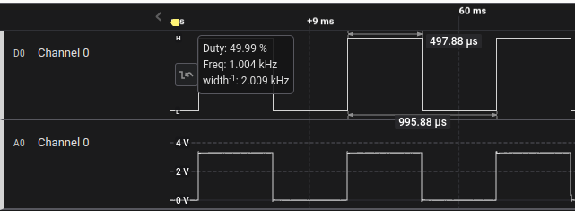
Great it’s almost exactly what we would expect the top is the Digital representation of the analog signal that is ont the bottom. Let’s see what happens when we divide it down by 4:
    // Set the duty cycle value
    pwm.set_duty(max_duty/4);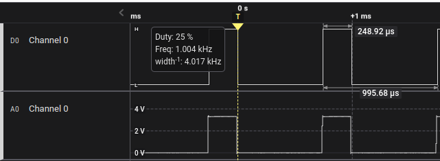
and here’s the final code:
#![no_std]
#![no_main]

use cortex_m_rt::entry;
#[allow(unused_imports)]
use cortex_m::{
    interrupt::{free, Mutex},
    peripheral::{NVIC}
};
use panic_halt as _;
use stm32l4xx_hal::gpio::gpiob;
#[allow(unused_imports)]
use stm32l4xx_hal::{
    pac,
    prelude::*,
    interrupt,
    delay::Delay,
    gpio::{Input, Edge, ExtiPin, gpioc::PC13, PullUp, gpioa::PA5, Output, PushPull},
    stm32
};

#[entry]
fn main() -> ! {
    // Get a singleton to the peripherals of our device
    let mut p = pac::Peripherals::take().unwrap();
    // Get a singleton to the CorePeripherals of our device. Coreperipherals differ from Peripherals
    // the CorePeripherals are common to the cortex-m family.
    let cp = stm32l4xx_hal::device::CorePeripherals::take().unwrap();
    // From my understanding the constrain method works to provide different methods from the HAL on each of it's members
    let mut flash = p.FLASH.constrain();
    // Acquire clock control handle
    let mut rcc = p.RCC.constrain();
    // Acquire power control handle
    let mut pwr = p.PWR.constrain(&mut rcc.apb1r1);
    // Set the system clock and the peripheral clocks and enables them via freeze.
    let clocks = rcc
        .cfgr
        .sysclk(80.MHz())
        .pclk1(80.MHz())
        .pclk2(80.MHz())
        .freeze(&mut flash.acr, &mut pwr);
    // Using GPIO B for the PWM output
    let mut gpiob = p.GPIOB.split(&mut rcc.ahb2);
    // Using channel 2 of the TIM2
    let c2 = gpiob.pb3.into_alternate(&mut gpiob.moder, &mut gpiob.otyper, &mut gpiob.afrl);
    // Create a pwm struct with a frequency of 1khz
    let mut pwm = p.TIM2.pwm((c2), 1.kHz(), clocks, &mut rcc.apb1r1);
    // Get the maximum value for the duty cycle configuration
    let max_duty = pwm.get_max_duty();
    // Set the duty cycle value
    pwm.set_duty(max_duty/4);
    // Enable pwm
    pwm.enable();
    loop {
    }
}
That’s going to be the end of this blog post I hope this helped.