Setting up an embedded rust project for STM32
Getting started with rust on the STM32
The purpose of this post is to give a brief overview of how to setup an embedded rust project and then to implement the helloworld of embedded systems. The famous blink demo. Let’s review what you will need to complete this course.
- Rust Toolchain installed on your target PC
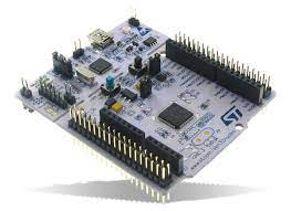
- An STM32 board preferrably one with an in built programmer and USB/UART converter like the NUCLEO series of board these can be bought for fairly cheap and in my opinion are much nicer than the Bluepill Many can be found here for reasonable cost
- A programmer if your board doesn’t have one, if you’ve bought a bluepill from amazon chances are this came in the package.
Target Installation
If you haven’t installed rust yet do so by following the directions on the official rust site: Rust Installation Instructions. The next step will be to install the proper cross-toolchain compiler for the chip that we’re using.
The cross-compilation target that is relevant for each board is listed below:
- Use thumbv6m-none-eabi for ARM Cortex-M0 and Cortex-M0+
- Use thumbv7m-none-eabi for ARM Cortex-M3
- Use thumbv7em-none-eabi for ARM Cortex-M4 and Cortex-M7 (no FPU support)
- Use thumbv7em-none-eabihf for ARM Cortex-M4F and Cortex-M7F (with FPU support)
You can find more information at the excellent cortex_m_quickstart docs
I will be using the STM32L476RG for the purposes of this tutorial but the instructions will be largely transferable to other chips. First we install the target.
# Using a Cortex-M4
rustup target install thumbv7em-none-eabi
Then we will want to install the cargo-flash utility this will help us flash the code we write to the MCU.
cargo install cargo-flashProject Initializaton
Now we will get started with making our project.
cargo new blinkyAnd now we will install our dependencies.
cargo add cortex-m cortex-m-rt embedded-hal panic-halt stm32l4xx-halThen we will add the correct feature flags for our MCU to the hal crate based on the board we are using in the end you will have something like the following:
# Cargo.toml
[package]
name = "blinky"
version = "0.1.0"
edition = "2021"

[dependencies]
cortex-m = "0.7.7"
cortex-m-rt = "0.7.2"
embedded-hal = "0.2.7"
panic-halt = "0.2.0"
stm32l4xx-hal = { version="0.7.1", features=[ "stm32l476", "rt"] }
Let’s breifly go through what each of the packages we just installed is doing for us.
- cortex-m
- This crate provides access to the Cortex-M core peripherals such as the NVIC and SysTick it will also provide us with tools for controlling interrupts and data access.
- cortex-m-rt
- This crate provides the startup code to run our program. For anyone familiar with the STM32CubeIDE this is roughly equivalent to the startup.s code that is generated for you.
- embedded-hal
- This provides some nice traits so that board crates can implement identical API’s.
- panic-halt
- This crate just provides a panic handler and makes it so that we don’t need to implement the panic handler ourself although it’s not much the entirety of the crate is the following:
#![no_std] use core::panic::PanicInfo; use core::sync::atomic::{self, Ordering}; #[inline(never)] #[panic_handler] fn panic(_info: &PanicInfo) -> ! { loop { atomic::compiler_fence(Ordering::SeqCst); } - stm32l4xx-hal
- This crate provides us with our MCU specifc HAL (Hardware Abstraction Layer). If you are using a different board you can find pany of the other HAL crates under the stm32-rs project
Now that we have our crates pulled in we have two last pieces of business until we can get to the fun part of actually writing code.
We will need to configure cargo to build our project properly so we set the build target appropriately and we will need to tell the compiler to use our linker script that well will create. You can find more information about this in the cortex_m_rt documentation.
# .cargo/config
[build]
target = "thumbv7em-none-eabi"
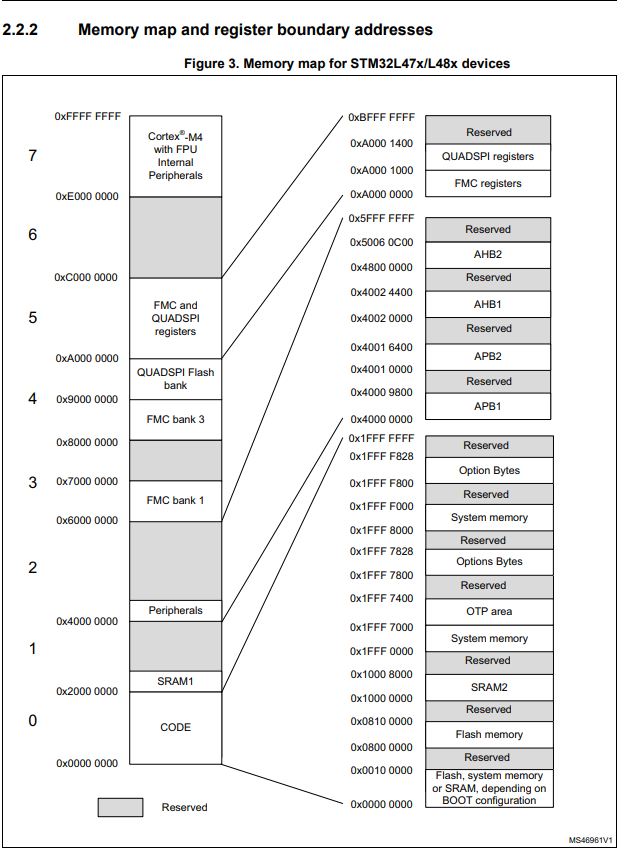
rustflags = [ "-C", "link-arg=-Tlink.x"]Lastly we will create a very basic linker script. This is baord specific. If you’re unfamiliar with microcontrollers this will always be found in you MCU’s datasheets or reference manual. A layout of the memory sections is provided below. By convention RAM starts at 0x2000000 and Flash starts at 0x80000000.
/* memory.x - Linker script for the STM32L476RGT6 */
MEMORY
{
  FLASH : ORIGIN = 0x08000000, LENGTH = 1024K
  RAM : ORIGIN = 0x20000000, LENGTH = 96K
}
Now with that complete we will finally write our code. We will use the HAL at first and then we will walk through exactly what each step is performing.
//main.rs
#![no_std]
#![no_main]

use cortex_m_rt::entry;
use panic_halt as _;
use stm32l4xx_hal::{
    pac,
    prelude::*,
    delay::Delay,
};

#[entry]
fn main() -> ! {

    let p = pac::Peripherals::take().unwrap();
    let cp = stm32l4xx_hal::device::CorePeripherals::take().unwrap();
    let mut flash = p.FLASH.constrain();
    let mut rcc = p.RCC.constrain();
    let mut pwr = p.PWR.constrain(&mut rcc.apb1r1);
    let clocks = rcc
        .cfgr
        .sysclk(80.MHz())
        .pclk1(80.MHz())
        .pclk2(80.MHz())
        .freeze(&mut flash.acr, &mut pwr);
    let mut gpioa = p.GPIOA.split(&mut rcc.ahb2);
    let mut user_led = gpioa.pa5.into_push_pull_output(&mut gpioa.moder, &mut gpioa.otyper);
    let mut timer = Delay::new(cp.SYST, clocks);
    loop {
        user_led.toggle();
        timer.delay_ms(500_u16);
    }
}
Our first step is to declare the following:
#![no_std]
#![no_main]
This tells the compiler that we will not be using the standard library only the core library. This means we must rely only on language primitives. It also tells the compiler that we will not be using the main function as the entry point into our application. The reason for this is that we must first bootstrap the runtime for our code to execute. The function specified by the #[entry] attribute will be called by the reset handler after initialization.
We get this attribute from the following line:
use cortex_m_rt::entry;Next we must specify the panic handling behavior of our code. We use the panic_halt crate to provide this for us. Now we can get to the good stuff actually programming our controller.
We will pull in the necessary items from our board level crate so that we can use them in our program.
use stm32l4xx_hal::{
    pac,
    prelude::*,
    delay::Delay,
};
pac gives us access to the peripherals of our device. prelude pulls in a number of different traits, that you will want to use when writing your code, and delay::Delay will allow us to use SysTick to create a nice delay for our project we could just as easily implement a simple timer ourselves, but we will look at that later on.
#[entry]
fn main() -> ! {
    // Get a singleton to the peripherals of our device
    let p = pac::Peripherals::take().unwrap();
    // Get a singleton to the CorePeripherals of our device. Coreperipherals differ from Peripherals
    // the CorePeripherals are common to the cortex-m family.
    let cp = stm32l4xx_hal::device::CorePeripherals::take().unwrap();
    // From my understanding the constrain method works to provide different methods from the HAL on each of it's members
    let mut flash = p.FLASH.constrain();
    // Acquire clock control handle
    let mut rcc = p.RCC.constrain();
    // Acquire power control handle
    let mut pwr = p.PWR.constrain(&mut rcc.apb1r1);
    // Set the system clock and the peripheral clocks and enables them via freeze.
    let clocks = rcc
        .cfgr
        .sysclk(80.MHz())
        .pclk1(80.MHz())
        .pclk2(80.MHz())
        .freeze(&mut flash.acr, &mut pwr);
    // On our board the LED is tied to the PA5 pin. So we will need to get access to the GPIO A bank
    // The registers for GPIO A are controlled by the AHB2 (Advanced High-performance Bus 2)
    let mut gpioa = p.GPIOA.split(&mut rcc.ahb2);
    // We configure the user_led to be a push pull output.
    let mut user_led = gpioa.pa5.into_push_pull_output(&mut gpioa.moder, &mut gpioa.otyper);
    // We create a delay timer using the SYST peripheral
    let mut timer = Delay::new(cp.SYST, clocks);
    loop {
        // We use the Toggleable trait to turn on and off the led
        user_led.toggle();
        // We delay for 500ms
        timer.delay_ms(500_u16);
        // Repeat
    }
}
If you’re not used to working with MCU’s or using, arduino, or vendor provided HAL’s a lot of these acronyms will seem opaque. MCU’s have a ton of nuance but don’t be afraid the documentation around these registers is often very good and is worth taking a look at.
For instance let’s take this line of code:
let mut user_led = gpioa.pa5.into_push_pull_output(&mut gpioa.moder, &mut gpioa.otyper);What on earth is gpioa.moder and gpioa.typer. Well these are registers that control the behavior of a specific GPIO pin. Let’s see what they do:
Here we see that the GPIOA_MODER register set’s the mode of the GPIO pins on BANK A.
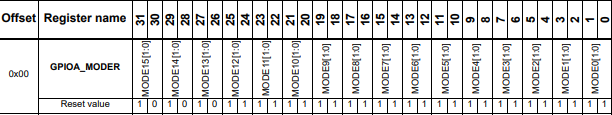
That mode is defined by the following bit’s:
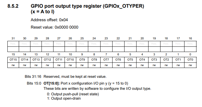
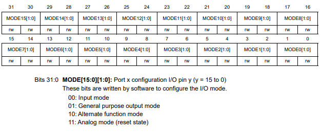 And lastly the type of output is defined here:
When you hear someone refer to bare-metal programming often what they are referring to is that instead of using a nice method like this:
let mut user_led = gpioa.pa5.into_push_pull_output(&mut gpioa.moder, &mut gpioa.otyper);They will individually mask the bits on each register.
The last step for this is flashing our code to the device.
$ cargo flash --chip stm32l476rg --releaseAfter that you should see the GPIO on your board flipping every 500ms, and with that we wrap up this post.